This view shows the rotor of the water pump with tufnol vanes. The pump was tested in the lathe at different RPM and pumped at all speeds even when turned at slow speed by hand.The tufnol proved to be unsuitable in that it was hydroscopic and jammed in the slots. These have been replaced with delrin which is not hydroscopic..
The components of the pump.
The pump with a coupling on the governor shaft. This will enable the pump to be removed without removing the timing case. The magneto is actually a distributor driven at crankshaft RPM. It has a twin lobed cam operating points and a two to one reduction gearing to drive the rotor. The rotor shaft has two ball races.
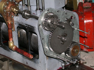
This is the govenor gear with the pivots for the fly weights. I have decided that it is unlikely to make this function in this scale so will just use the governor shaft to control the engine RPM manually.
The fan hub was made by machining four curved grooves in the hub. The toolpath was initially drawn in AutoCAD and a dividing head used to repeat the groove at 90 degrees. The curved blade mounts were machined from a piece of steel tube (turned to the correct diameter and thickness) and cut length-ways to size.
These were silver-soldered in to the slots and the sheet metal blades riveted on.
The fabricated casting on top of the timing case is the housing for the governor spring.
The crankcase covers removed showing the crank and connecting rods.


Awesome 60!
ReplyDelete