Saturday, March 31, 2012

Cam shaft and timing case gears

This image shows setting the position of the cams on the table of the mill. The shaft is held in the chuck of the dividing head and supported by the centre at the other. The dividing plate has 3300 holes for direct indexing  clock wheels. For this application I choose the outer row which has 288 holes. The plate was first marked in quarters, then marked 92 holes either side of these marks. A "Y" shaped tool which comes out of a battery drill kit for driving cup hooks was used to locate each cam in the correct location by the index plate. Care was needed to not only have the firing order correct (1-2-4-3) but also set the cams for the right sequence as the exhausts are on the outside of the engine on 1 and 4 but in the centre together on 2 and 3. The cams were locked in position by 3mm grub screws and loctite.

Hobbing the crankshaft gear from silver steel. This gear has a keyway for location and will be oil hardend.


This image shows the camshaft gear being hobbed.


Here the gears are mounted in position. The small 13 tooth gear, which is driven from the large cam shaft gear, drives the fan. In the prototype the gear train is 38, 76 ,38 and 16  on the fan. I have selected 30, 60, 30 and 13 which fit the centre distances in the model with availiable hobs. The fan shaft is 6mm in diameter and runs in a 6mm by 13mm ball race next to the gear. The missing gear to the top left drives the water pump and magneto (on the model it will be a distributor).

Saturday, March 24, 2012

Connecting Rods

This is the schematic of the crankshaft and camshaft showing the clearance for the connecting rods. The stroke is 40mm the connecting rod is 91mm between centres.

I plan to cut a trial connecting rod and dummy piston from aluminium to check clearances. The connecting rod big ends actually run between the cam lobes for each cylinder so the mock-up con rod will be used to confirm the clearance.


This was taken as a screen capture from AutoCAD. The horizontal blue dashed lines are the Y limits of the mill and the red dashed lines are the Mill table centres.

Monday, March 19, 2012

Crankshaft

The crank is made from a length of 64mm 4140 steel bar. The bar was set up in the lathe on a fixed  steady so that both ends could be centre drilled. The bar was next clamped in a vice which had been set up accurately so that the bar would be parallel to the axis of the horizontal spindle. A centre drill set up in the collet of the horizontal spindle was used to adjust the knee and the table so that the centre was accurately located. The centre was then drilled slightly deeper to ensure a perfect alignment. Two holes were then drilled 20mm either side of the centre. A flat was machined across the bar for a reference to drill the other end of the bar using a dial indicator.

To cut each crank throw, three pockets 14mm wide by 20mm deep were milled at each cylinder centre line. This left a rectangular block at each throw of the crank 23mm wide by 43mm deep. A long slot drill was used to reduce these blocks to 23mm square ready for the next machine step..


The shaft mounted on its centres in a dividing head. The throws (23mm squares) were made round using a long 8mm, ball nosed carbide slot drill and by hand cranking the dividing head.


The cheeks were faced in the lathe using a boring bar. The lathe was run slowly since the crankshaft is not balanced when machining the big-end journals.The centres will be lost when the ends of the shaft are machined.


The partially finished crankshaft and camshaft. The journals will be ground down to 21.9mm.

Saturday, March 10, 2012

Rockers and cams

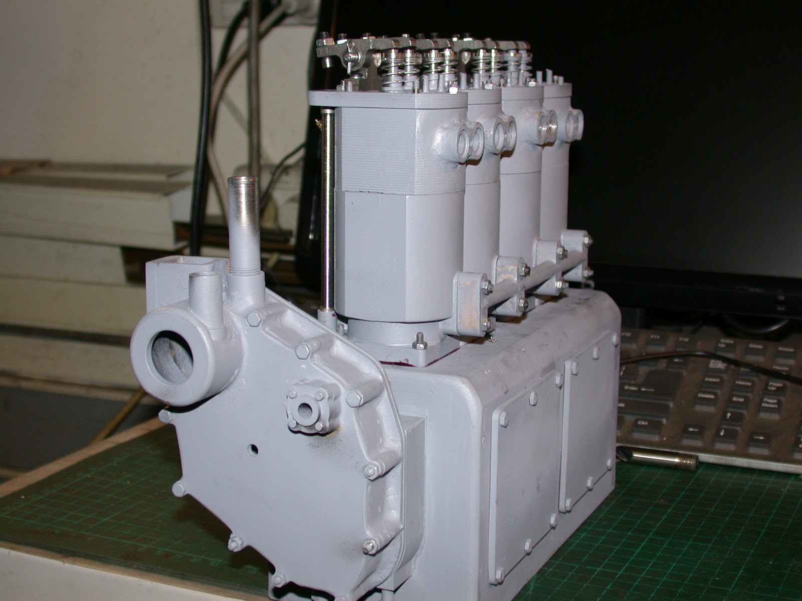
Rockers installed on heads.The sleeves have been inserted in the barrels with an o ring at the bottom  and locktite 515 sealant at the top.


Individual cam being machined from silver steel.The cams have  30mm radius flanks and a 10mm bore to fit on a 10mm 4140 steel shaft.Each cam has a 5mm wide flange which is threaded 3mm for a grub scew.


Loose cams after machining and some blanks that have been bored and reamed 10 mm. A slot has been machined to separate the cam from the flange.


This image shows number 4 cylinder with 2.2 mm push rods installed.The tappet adjusters are made from high tensile hex 4mm bolts.  A hemi spherical cavity is machined into the heads and the hex turned off. The push rods have domed ends and are made from music wire .The bottom of the pushrods fit into 6mm deep holes in the cam followers


Note the angle on the radiator which is due to the suspension springs not being strong enough to take the weight of the engine. The springs will need to be much stronger to support the additional weight of the flywheel and crankshaft