Saturday, January 13, 2024


 This is my current project .,a 1/5th scale model of a 1913 AHMcDonald tractor.

Since October 2012 I have built a Murdock and Aitken steeple engine and a model of a" Cane crushing engine "

I also made 4 CNC milling machines

I will add details of these projects in future This is the twin cylinder petrol engine I built for this tractor

Tuesday, November 14, 2017

Hobbing a 2 mm Diameter 5 leaf pinion

The video shows a hobbing machine based on an article that appeared in the "The Model Engineers Workshop" magazine in 2003.In this article a 20 to 1 dividing head was controlled by an encoder driven from the hob arbor .The summary at the end suggested that the system was unlikely to work with a 40 to 1 dividing head .As you would be aware I used this system to cut the gears for the model  using a 90 to 1 rotary table.This system was used to cut 2,25 module final drive gears in 4140 steel for the final wheel reduction gear box on a "Bob Cat " tractor.
The video is of a smaller machine for cutting watch and clock wheels from 0.5 to 0.19 module

Wednesday, October 3, 2012

Draw bar

 The two components to make the draw bar where made with two identical pieces.The reinforcing rib and bosses around the holes were CNC milled from 7mm flat plate and then each was cut to shape.These were then bent by heating with oxy acetylene .The two pieces were brazed together with a packing piece. All the surfaces were cleaned and fluxed so that the bronze filler rod flowed between the joints.


 The completed bar.


                                                                                                                                                                                                                                                   The pivot bolt has a castellated nut which was machined with a 1.5mm four flute carbide end mill on a Steinel mill drill . The indexing was achieved by clamping the nut in a 25mm tool room vice.                                                                                                                     

Saturday, September 15, 2012

Radiator, sign writing and water manifold

 Cutting out the flanges for the water outlet manifold on a BCA mill  modified to CNC.Cutter is 1.5mm.four flute carbide running at approximately 10,000 rpm with a feed rate of 100mm per minute.The nozzle is compressed air to keep the cutter free of chips.


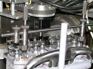
 This image shows a trammel being used to measure the precise location of each of the water outlets from each cylinder


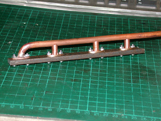
A strip of mild steel was jig drilled to duplicate the position of each outlet of the cylinders and the holes of the studs.This was the jig used to hold all the components of the manifold  for silver soldering.

This is the modified ubolt bender used to bend the 8mm copper tube.


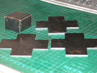
These shapes were made to form the tappet covers.
The cowling for the radiator was formed by two components, a flat sheet and a rolled strip.The flat plate had a hole cut in the centre then 12 flolds to form the shape.The ring was silver soldered in position Heat shrinking was required to reduce the outside of the cowling to fit the radiator


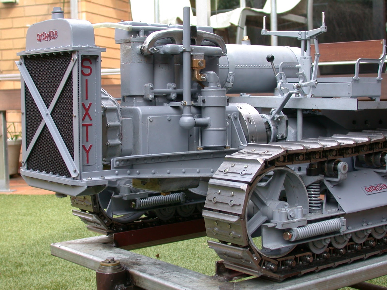
These two images show the model as at 16 -9-12
I plan to take the model to the 100th rally at Lake Goldsmith in November this year.

.


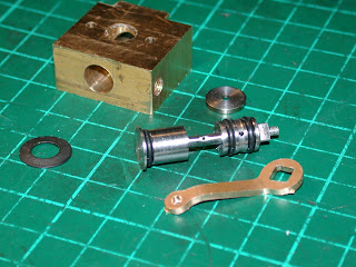
This is the body,and butterfly for the throttle. The main jet is 0.8mm drilled in the butterfly and fuel enters this jet through a hole between the two o rings.This component is made from 303 stainless.

Thursday, August 30, 2012

Carburettor


 Progress came to a stop as while I drove the engine on the bed of my mill by belt large amounts of oil was pumped to the top of the cylinders.The engine was completely dismantled.The cause of the problem was the piston skirts protruded 7mm below the bottom of the sleeves. I reduced the pistons by 7mm and installed oil rings on the bottom of the skirts.


This image shows the support for the air intake and air cleaner brackets  which were cut from brass using CNC.


The two halves were silver soldered together and shaped with file and Dremel .The butterfly was machined from 303 stainless. This is the bottom section of the carburettor and would normally be the choke


 The block above this section would normally be the float chamber and throttle valve.
Initially I will attempt to run the engine on petrol gas using this butterfly as the throttle and use the air cleaner to vapourise the fuel,
                                                                                      

Thursday, June 28, 2012

Manifolds,magneto and sparkplug leads

 This is where the model is up to now, the carburettor,air cleaner and dummy hot box are to be made.The rocker covers and water out manifold are also to be fabricated.
 The inlet manifold is now installed.Note the diamond shaped clamps

The right hand side of the engine.The fabricated casting on the side of the timing case is for the governor spring . On this model the governor will not work. The fan cowling is yet to be made

Saturday, June 23, 2012

Inlet and Exhaust Manifolds.

Originially Caterpillar cast the manifolds, something I was not prepared to do at this scale. Instead I fabricated the exhaust in two halves (inner and outer) to form the 'tube'. This shows machining the internal passages, from each of the cylinder heads, for the inner half (head side). The other side is a mirror image.
Here the outer profile is being machined. The manifold is being cut from mild steel. The cutter is a 6mm four flute solid carbide roughing cutter running about 5000 RPM and a feed rate of 200 mm/min.
This is the reverse side showing the ports being machined.
Here are the two halves ready for welding. Once welded the manifold is hand filed to profile. 
A similar process was applied to the inlet manifolds. In this case they were made from brass. I chose this because it is easier to machine since the inlet manifold is also more complex. Here is one manifold silver soldered and the other pair before. Much machining and hand shaping is still required before these are finished.
 Including filing the exhaust manifold has taken about six hours. Fitting to the heads took about the same again! Here you can see the partially completed inlet and exhaust manifolds mounted.
Note the diamond-shaped clamp plates holding the manifolds to the heads.