 The splined input shaft, gear cluster and gear box end cover.
 The cover was machined in the lathe to maintain the tight tolerance required
 This is the final drive gear being machined from K1045 steel. It has 73 teeth 1.5 module. This gear gets bolted to the hub of the drive sprocket.
 Here is the drive sprocket, final drive gear and drive pinion attached to the steering brake drum and drive clutch spline which receives the clutch spider.
 The drive pinion installed in the transmission and the final drive gear with the sprocket removed. The cover plate mount is also in position.
 The inside profile of the clamp plate has been finished. About to cut the final shape.
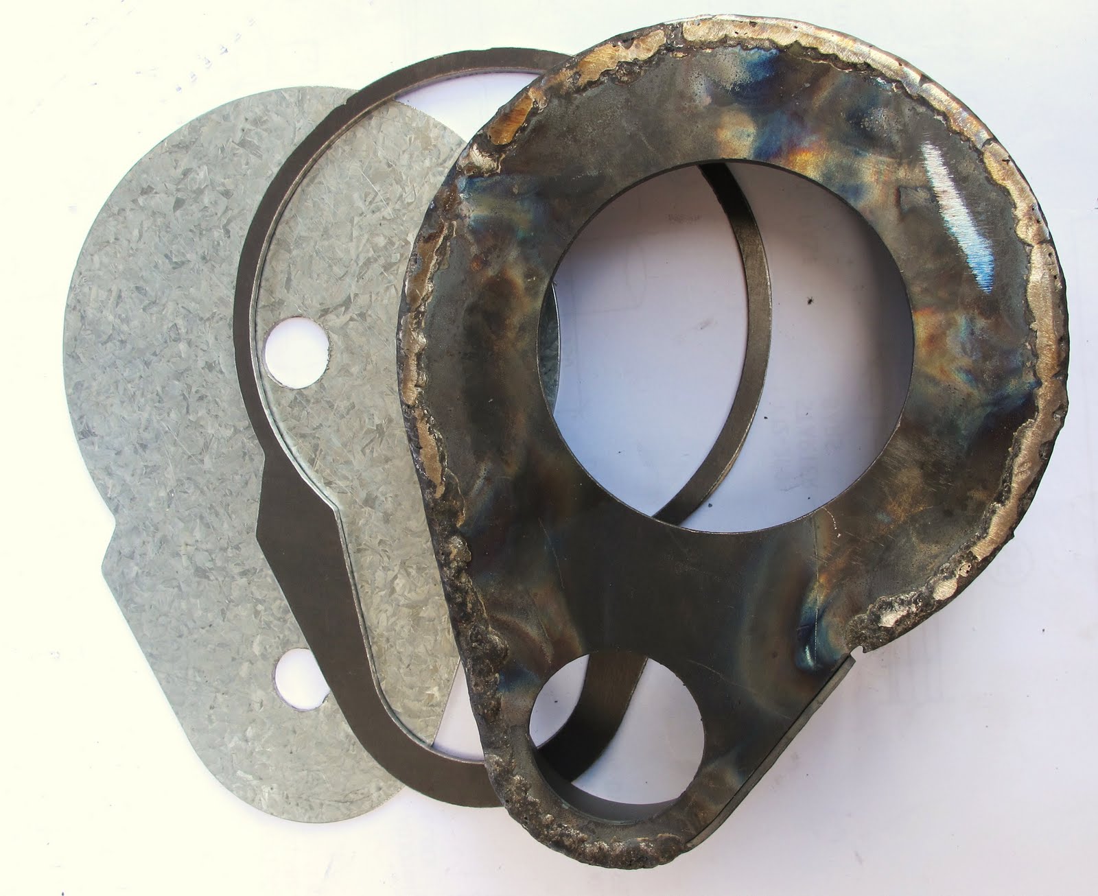 Behind is the transmission mount plate, then the clamp plate (from above) and the gear cover partially fabricated using oxy welding and monel filler wire. This was done for strength so that it did not fall apart on subsequent operations. The mounting plate and ribs (shown later) were brazed on.
  Left and right gear covers. Showing right hand cover (on left) before fabrication.
 Here is the cover in place. Also seen here is the drive hub with studs where the drive sprocket attaches.
 The completed cover temporarily fixed with cap screws to the transmission. These screws will be replaced with hex headed 3mm bolts.
Note the cap bolted to the outside of the cover. This houses the outer pinion ball-race.


