Thursday, August 30, 2012

Carburettor


 Progress came to a stop as while I drove the engine on the bed of my mill by belt large amounts of oil was pumped to the top of the cylinders.The engine was completely dismantled.The cause of the problem was the piston skirts protruded 7mm below the bottom of the sleeves. I reduced the pistons by 7mm and installed oil rings on the bottom of the skirts.


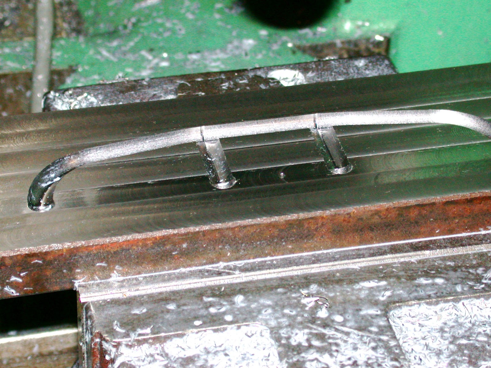
This image shows the support for the air intake and air cleaner brackets  which were cut from brass using CNC.


The two halves were silver soldered together and shaped with file and Dremel .The butterfly was machined from 303 stainless. This is the bottom section of the carburettor and would normally be the choke


 The block above this section would normally be the float chamber and throttle valve.
Initially I will attempt to run the engine on petrol gas using this butterfly as the throttle and use the air cleaner to vapourise the fuel,
                                                                                      

Thursday, June 28, 2012

Manifolds,magneto and sparkplug leads

 This is where the model is up to now, the carburettor,air cleaner and dummy hot box are to be made.The rocker covers and water out manifold are also to be fabricated.
 The inlet manifold is now installed.Note the diamond shaped clamps

The right hand side of the engine.The fabricated casting on the side of the timing case is for the governor spring . On this model the governor will not work. The fan cowling is yet to be made

Saturday, June 23, 2012

Inlet and Exhaust Manifolds.

Originially Caterpillar cast the manifolds, something I was not prepared to do at this scale. Instead I fabricated the exhaust in two halves (inner and outer) to form the 'tube'. This shows machining the internal passages, from each of the cylinder heads, for the inner half (head side). The other side is a mirror image.
Here the outer profile is being machined. The manifold is being cut from mild steel. The cutter is a 6mm four flute solid carbide roughing cutter running about 5000 RPM and a feed rate of 200 mm/min.
This is the reverse side showing the ports being machined.
Here are the two halves ready for welding. Once welded the manifold is hand filed to profile. 
A similar process was applied to the inlet manifolds. In this case they were made from brass. I chose this because it is easier to machine since the inlet manifold is also more complex. Here is one manifold silver soldered and the other pair before. Much machining and hand shaping is still required before these are finished.
 Including filing the exhaust manifold has taken about six hours. Fitting to the heads took about the same again! Here you can see the partially completed inlet and exhaust manifolds mounted.
Note the diamond-shaped clamp plates holding the manifolds to the heads.

Pump, Governor, Fan, Distributor

This view shows the rotor of the water pump with tufnol vanes. The pump was tested in the lathe at different RPM and pumped at all speeds even when turned at slow speed by hand.The tufnol proved to be unsuitable in that it was hydroscopic and jammed in the slots. These have been replaced with delrin which is not hydroscopic..
The components of the pump.
The pump with a coupling on the governor shaft. This will enable the pump to be removed without removing the timing case. The magneto is actually a distributor driven at crankshaft RPM. It has a twin lobed cam operating points and a two to one reduction gearing to drive the rotor. The rotor shaft has two ball races.
This is the  govenor gear with the pivots for the fly weights. I have decided that it is unlikely to make this function in this scale so will just use the governor shaft to control the engine RPM manually.
The fan hub was made by machining four curved grooves in the hub. The toolpath was initially drawn in AutoCAD and a dividing head used to repeat the groove at 90 degrees. The curved blade mounts were machined from a piece of steel tube (turned to the correct diameter and thickness) and cut length-ways to size.
These were silver-soldered in to the slots and the sheet metal blades riveted on.
The fabricated casting on top of the timing case is the housing for the governor spring.

The crankcase covers removed showing the crank and connecting rods.

Saturday, June 2, 2012

Pistons and rings

 The pistons have been machined from cast iron. The inside of the piston has been pocketed with a 4mm end mill.Note the fixture top left which is used to hold pistons for finishing the outside and ring grooves
 This image shows the pistons with ring grooves machined and gudgeon pin holes bored.The rings have also been machined with a slit made by a 0.2 mm saw. The ring in the foreground has been heated to dull red with a 4mm nut in the gap. Only two ring grooves have been cut both for compression ,no oil rings at first. These will be added later if found necessary.
Three pistons ready to be installed . The gudgeon pins are oil hardened silver steel. Teflon buttons on both ends of the pins prevent the pins from scoring the bore

Thursday, May 17, 2012

Big end bearings

The big end bearing surfaces were tinned with white metal using a soldering iron.The caps were installed on the rods with 1mm. aluminium shims. Both sides of the big ends were then filed flat. Two thick aluminium washers were made to contain the white metal.The white metal ingot was melted and poured slowly into a bucket of water to form granules. These granules were packed into the big end  space between the aluminium washers clamped very tight with a 5mm. bolt This must be a water tight seal to retain the molten bearing metal. The rods were spun in the lathe on the fixture previously shown.Melting of the metal was acheived using a Mapp gas torch while the rod was spun at about 1000 rpm.
Potentionally this is a dangerous operation.
The result was excellent as the metal is solid and all impurities finish up on the inside.Using the same fixture the big ends where bored to fit the crank journals
The block on the caps used in the manufacture were drilled and reduced to make oil scoops for  oiling.


Friday, May 11, 2012

Connecting rods

 Profiling the rods with the blank screwed on a  scrap piece of steel.
The  profiled rods caps and mountiing block
 The caps super glued to the rods to enable the rods to be drilled and tapped 3mm.
Tapping the rods

The rods bolted together to enable the big ends to be pocketed. Note the jig used to hold the rods.The small end has been reamed  6mm to fit on a 6mm dowell, the big end cap is held in a small Starrett vice which is screwed in a slot in the plate to enable the rods to be accurately aligned.
This rod has been bored.


 Using the same jig the rods have been tapered and fluted
The same jig mounted on the face plate will be used to centrifically cast the white metal for the big end bearing. The final boring of the bearing will be turned on this jig.