Saturday, January 29, 2011

Steering Brakes

The brake bands are strips of phos-copper.


This shows the band arround one of the clutch drums these strips are fixed to the bottom by 5mm set scews.


These are the brake parts. There are two finished brake levers, one attached to the bell-crank shaft the other is the bell-crank attached to the block which links on to the brake band.

There is also a finished brake lever cover and mount block, plus the parts for the second cover before fabrication. The 'H' is bent to the correct angle and brazed onto the rectangular plate which forms the flange for mounting.After the ends have been brazed on the strake of the H is filed down before the top is also brazed.


The right hand steering brake lever mounted on its shaft. The cover casting is yet to be fitted. This lever was profiled from 10mm steel by CNC. The fluting was milled with a 2mm slot drill
Hand filing was used to achieve the taper, finally the lever made red hot to give it the correct set.


Set up for drilling the lever for the 3mm clamp screw.


Steering Clutches

This is one of two clutch release forks being profiled, and slots machined for the pivot links, out of 10mm mild steel on the mill. Once finished here they had to be cross-drilled for the pivot and hinge pins.


Here is one of the bare steering forks in situ on a steering clutch assembly.


This is the entire drive axle showing the steering clutches, one dismantled including a dis-assembled throw-out bearing (shown in the Gearbox post).

When the steering clutches are disengaged, although the force on the ball races is high, the friction on the drive shaft is minimal.


This shows the assembled drive shaft within the transmission.
Each throw-out fork pivots on two links that attach to one of the main bearings. The thust when releasing the steering clutch is taken between the throw-out bearing and the main bearing. These are linked by a 30x3mm plate that links the two main bearing supports.


This is the base of the driver's seat mounted to the top of the transmission. Directly below this are the bearing stands for the steering cams. They can also be seen below with the transmission cover partly removed.


The transmission cover has been removed to show the transmission. The steering forks have swivel blocks on which the cams act. The swivel blocks have counter sunk holes bored in their tops, this is to lubricate the pivots and the trunion.


This is the underside of the transmission cover showing the cams (the two egg shapes in the middle) which push against the captive rectangular bars. The outer ends push on the swiveling blocks (shown in the previous picture with oil hole).

Friday, January 28, 2011

Mud Guards

The mud guards started as a length of 25x3mm angle cut down to 16x2mm. This had to be rolled to the shape of the guards to support the sheet metal. The inner angle was bent, flange down, to attach the vertical sheet to the flat tops. The outer angle supports the flat tops on the outside and was bent flange up.


The sheets are riveted to the angles with round-head 3/32" steel rivets. The steps are also riveted. The vertical sheets are bolted to the transmission. They are also supported at the rear by two threaded bars.


The mud guard shown from underneath.


From the top with the roughed out foot plate in place.

Equalizer Beam


This beam was started from a 'T' section
bent and welded to form the correct shape. The web of the 'T' section was shaped and the bottom flange was made from a flat strip brazed on. The ends were machined from round bar. This photo shows the bottom flange about to be brazed the cups for the springs are yet to be added.


This is the equalizer beam with spring cups brazed on and the pivot beam attached.


Here is the equalizer beam installed under the engine frames.


This is the view underneath showing the spring cups sitting on the track frames and the pivot beam attached to the engine frames. The equalizer beam pivots on this.


Here you can see through the transmission. The pivot beam brackets, engine beams and front engine mounts have been riveted.


A close-up of the ends of the equalizer beam showing it assembled with springs.


This is a view of the engine beams. The radiator will mount to the front most angles.

Note the model has minimal fastenings at this stage as it will need to be pulled apart for painting.


Saturday, December 25, 2010

Annual update

This picture is where the project is at this time and represents 12 months work. The turning clutch disengagement mechanism, the gear selectors and turning brake levers will complete the transmission.
The final reduction gears are complete in their housings.


This is the equalizer beam being fabricated.The engine beams and the front suspension have been completed.


This image is not recent but shows a view not available to owners of the full size tractor.


The equalizer beam is now mounted to the engine frames. The engine frames are made from angle riveted to 2mm plate steel.
In this image the brackets to mount the channels to carry the pivot axle have not been riveted in place.

Friday, December 10, 2010

Transmission - Case

This is the drawing from the parts book that was used to dimension the transmission. Measurements were also taken from the prototype in Queensland.


The transmission started out as a piece of 65mm pipe, 5mm wall thickness. It was cut to length (240mm) and carefully quartered on a large bandsaw.


Here I am in my friend Bob Waterford's workshop making the final cut.


Here are the two quarters of pipe separated by a piece of 6mm plate 240x50mm. This was welded together to form the base of the transmission. The remainder of the transmission was fabricated in a similar way.


This photo has been posted previously and shows the fabrication of the transmission complete.

The fabricated transmission was placed on a surface plate upside down to mark out the bearing centres. It was then clamped to the mill table and the holes bored.


Saturday, November 20, 2010

Final Reduction Gearbox and Cover

The splined input shaft, gear cluster and gear box end cover.


The cover was machined in the lathe to maintain the tight tolerance required


This is the final drive gear being machined from K1045 steel. It has 73 teeth 1.5 module. This gear gets bolted to the hub of the drive sprocket.


Here is the drive sprocket, final drive gear and drive pinion attached to the steering brake drum and drive clutch spline which receives the clutch spider.


The drive pinion installed in the transmission and the final drive gear with the sprocket removed. The cover plate mount is also in position.
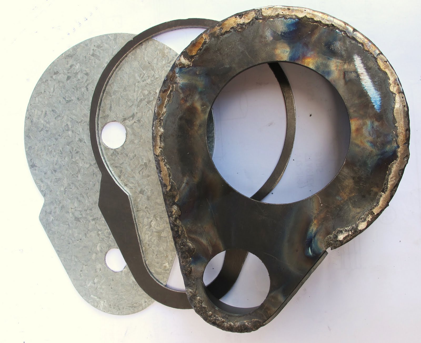


The inside profile of the clamp plate has been finished. About to cut the final shape.


Behind is the transmission mount plate, then the clamp plate (from above) and the gear cover partially fabricated using oxy welding and monel filler wire. This was done for strength so that it did not fall apart on subsequent operations. The mounting plate and ribs (shown later) were brazed on.


Left and right gear covers. Showing right hand cover (on left) before fabrication.


Here is the cover in place. Also seen here is the drive hub with studs where the drive sprocket attaches.


The completed cover temporarily fixed with cap screws to the transmission. These screws will be replaced with hex headed 3mm bolts.


Note the cap bolted to the outside of the cover. This houses the outer pinion ball-race.