Progress this past month ceased due to computer and hardware problems .I now have the system running on Windows 7 via a Smooth Stepper, which is availiable from Peter Homann Designs. This hardware allows the system to run from the USB .The new computer has a parallel port which runs the Rutex drivers but would not drive the Gecko 540 .Modern PC computers can be fitted with a parallel port .A plug in board is availiable for about $14 but is not suitable to run CNC drivers. The smooth stepper is powered from the USB but can easily be powered from a 5volt regulated supply. This should make it possible to run CNC machines from a laptop. The smooth stepper's output is two parallel ports. The stepper motors run very much quieter with this system.
The intermittent problems with the y axis on both my CNC mills have been located and rectified.The plug on the servo driver board had a loose connection and one of the wires to the stepper motor had been sheared by the grub screw.In both cases these caused catastrophic destruction of the job and tool breakage
.
This image shows the tool path for the back plate of the engines timing case.These apertures are the position of the crankshaft at the bottom , the fan drive directly above,the camshaft to the left and above and the magneto drive on top.The prototype has 38 teeth on the crank 76 on the camshaft,38 on the magneto drive and 18 on the fan which is driven off the camshaft gear. The design of the model engine had to be based on the crakshaft being in line with the input shaft of the gearbox and the fan to be in the center of the radiator.To achieve these position I have chosen 1 module gearing ,30 , 60 , 30 and 14 teeth.
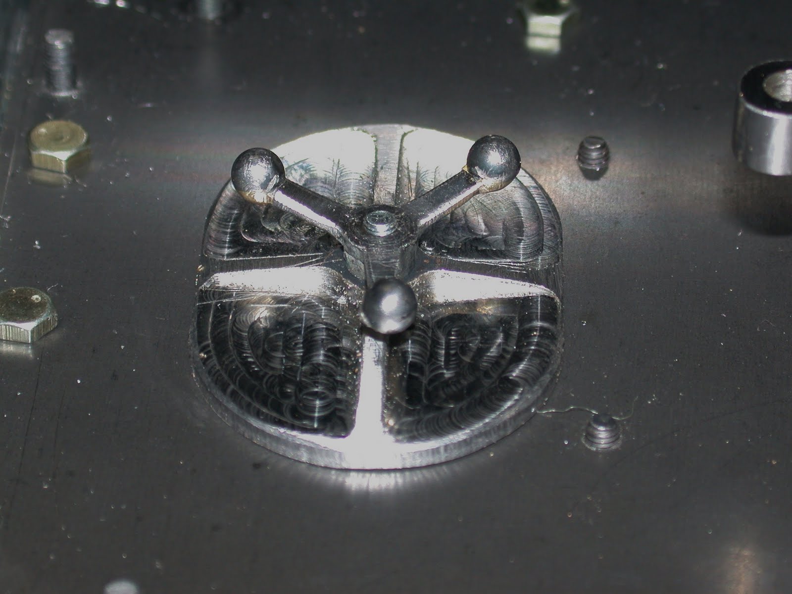
Now that these shaft positions have been set the engine can be designed.The timing case has now been fabricated as in image below.The cylindrical housing is the cover for the governor, the other protrusion is the fan shaft bearing. The tube at the top is the breather for the engine which is also where the engine is filled with oil.The cover was brazed using manganese bronze filler wire which simulates the fillets of a casting.Shot blasting will further make the cover look as if it were a cast.
Saturday, September 17, 2011
Monday, August 1, 2011
Main Clutch
The main frame was machined from 100 mm en25 bar with a cermet tip tool . A very tedious job on a small lathe.This frame is threaded for the spider which allows for adjustment for wear of the clutch plate .Note the bronze bush which is the bearing for the clutch plate. The clutch plate was profiled from 3.2 mm gauge plate. The plate is faced with leather.To assemble the clutch the plate is fitted first, next the splined nut which is pinned to the frame ,then the drive plate( which has a matching spline) is placed
This image shows the spider which was first threaded in the lathe so that it could be mounted on the frame for machining. It has four slots for the cams .In one of the slots there is slit to the thread. A bolt across this slit clamps the spider
Thursday, July 7, 2011
Radiator
Friday, June 24, 2011
Brake and Steering Controls.
Note the steering arms are very close to the design of the prototype.
Saturday, May 28, 2011
Preliminary Painting
Gear Selector
Transmission Manhole Cover
Subscribe to:
Comments (Atom)