Friday, June 24, 2011

Brake and Steering Controls.

These are the components for the brake and steering linkages. The clevises are machined flat, then bent to shape red hot. The prototype clevises appear to be made by drop forging. Once formed they are brazed to the rod using silver solder flux and manganese bronze filler wire.


This picture shows the components of the steering stand, the steering arms, linkage parts and levers. The base of the stand and the web were cut out by CNC. The rest of the stand and the steering arms were made on the lathe and using hand tools.
Note the steering arms are very close to the design of the prototype.


The steering stand assembled (brazed).


This image shows the brake pedals on the shaft that operates the right hand turning brake, the left hand brake pedal hinges on this shaft and has the actuating lever attached.


The brake pedals were CNC machined from 6.5 mm steel plate, the treads were fluted using a D bit and then brazed on. The pockets on the sides of pedals were machined to 1mm deep using a 1mm diam 4 flute carbide end mill at 8000 RPM at a feed rate of 100 mm per minute cutting 0.25mm per pass with 40% cut over. This cutter has performed remarkably well considering the slow RPM


The right hand bell crank was also pocketed with the 1mm cutter.


The left hand side of the brake shaft is the axle for the main clutch lever.


The rear of the tractor showing the brake linkages coupled.

Saturday, May 28, 2011

Preliminary Painting

The model has been painted grey in a satin finish. Prototypes were painted this colour to facilitate photography. The parts were etch-primed before using an airbrush to paint them.


The tracks will be immersed in a mixture of colloidal graphite and white spirit. This will help with lubrication. They will then be painted.


Gear Selector

The gear lever installed. There are three forward gears and reverse in an H pattern. The gears are locked in neutral with spring loaded pins. Moving the gear lever left or right acts on these pins which releases the interlocks - as in the prototype.


Here is the underside of the gear selectors. The forks are CNC machined from gauge plate. They are attached to steel blocks which slide on 4mm steel bars. The detents which hold the gears in mesh are machined in these blocks.

Transmission Manhole Cover

This is the left manhole cover for the transmission. There is another matching plate on the right. They give access to the steering clutches.


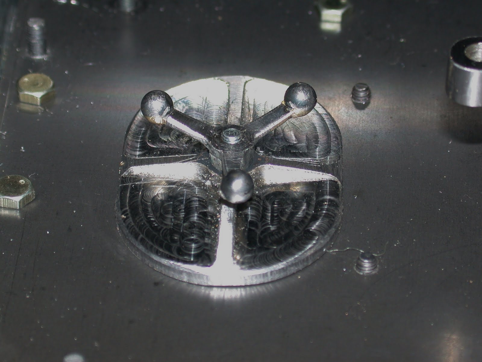
The hand wheel was initially threaded on the lathe and the spokes cut on the mill in a vertical chuck. The spokes were drawn in AutoCAD.


This was the jig used to braze the ball bearing onto the spokes. The jig is made from a graphite block and was jig-drilled to hold the balls in the correct position.


The finished cover before painting. The covers were machined out of 4mm steel. The ribs were machined before the outer profile was cut. The taper was hand filed.

Wednesday, March 30, 2011

Petrol tank

The tank brackets in position.


This photos shows a hand press modified to press dummy rivet heads on strips of brass to solder onto the copper tube to give an impression of a lap seam on the tank. The tube is hard copper which will be soft soldered so that the tank will be resistant to dents.


The ends of the tank have been rolled in a jenny made for this operation to form a ledge on the inside of the tube. Discs of copper were placed on these and soldered to form the tank ends. The rolled ends simulate the rolled ends of the prototype tank.


The prototype tank was made with two sheets of steel with two riveted seams.

Petrol tank

This is a mandrel to face off the 100 mm copper tube ,it is a 20 mm steel bar centred both ends supported by the lathe centres.
A disc has been loctited onto the bar
(next to the tail stock).The disc has been turned to the inner diameter of the tube.
A steel ring has been bored to fit over the outside of the tube.


The tube is fitted over the mandrel, supported
by the disc at the tailstock and driven by the
inside of the tube being supported by the ring.


This is the tool path for the webs of the tank
supportsThese webs set the position of the
tank and were used as the basis to braze the
additional parts that make up the mounts.


The two mounts fabricated and in position


Friday, February 25, 2011

Seat

First the side of seat had to be drawn, I use AutoCAD LT from 1993. This photo was used to draw the outline of the seat casting by enlarging it to A4 . Using measurements off the full size allowed me to scale from the photo. Before going near AutoCAD I started by drawing a vertical line along the front of the casting on the photo copy, a second horizontal line along the bottom of the casting .
A number of lines were then drawn by placing a ruler on the photocopy and drawing an extended line to pass through straight sections on the copy to intersect the base line,even the shortest sections were drawn in this way. The next step was to measure the actual distances from the front of the casting to the intersections of all the lines previously draw. The drawing can now commence in AutoCAD drawing the front vertical line and using the offset command to place all the other lines at the predetermined distances ( seven lines in this case ). The top of arm rest is parallel to the base line and can be placed in position, the casting has no right angles so it is necessary to measure each angle that all eight lines ( including the angle the front of the casting makes to the baseline). Using the rotation command the parallel array of lines can be made to run along the straight sections of our model casting. The curved sections of the drawing are completed using the fillet command, adjusting the radius by scaling off the photo copy and a little trial and error. The mounts were added to give the final outline.

This is a 1928 model Sixty showing the front detail of the driver's seat.


This is the screen showing the code to machine pocket.
The model has a 1mm rib following the outline of the casting. This was achieved using the offset command which results in the outline of the pocket.
The tool path for the second casting was mirrored in SheetCAM.


The pocket was machined first.


Cutting the outer profile. Each casting took about half an hour to cut. I mention this as there is a reluctance for some to embrace this technology. From starting the drawing to the first completed casting took a day.


The finished seat still needs upholstering and arm rests.


Here is a comparison between full size and scale