Saturday, December 25, 2010

Annual update

This picture is where the project is at this time and represents 12 months work. The turning clutch disengagement mechanism, the gear selectors and turning brake levers will complete the transmission.
The final reduction gears are complete in their housings.


This is the equalizer beam being fabricated.The engine beams and the front suspension have been completed.


This image is not recent but shows a view not available to owners of the full size tractor.


The equalizer beam is now mounted to the engine frames. The engine frames are made from angle riveted to 2mm plate steel.
In this image the brackets to mount the channels to carry the pivot axle have not been riveted in place.

Friday, December 10, 2010

Transmission - Case

This is the drawing from the parts book that was used to dimension the transmission. Measurements were also taken from the prototype in Queensland.


The transmission started out as a piece of 65mm pipe, 5mm wall thickness. It was cut to length (240mm) and carefully quartered on a large bandsaw.


Here I am in my friend Bob Waterford's workshop making the final cut.


Here are the two quarters of pipe separated by a piece of 6mm plate 240x50mm. This was welded together to form the base of the transmission. The remainder of the transmission was fabricated in a similar way.


This photo has been posted previously and shows the fabrication of the transmission complete.

The fabricated transmission was placed on a surface plate upside down to mark out the bearing centres. It was then clamped to the mill table and the holes bored.


Saturday, November 20, 2010

Final Reduction Gearbox and Cover

The splined input shaft, gear cluster and gear box end cover.


The cover was machined in the lathe to maintain the tight tolerance required


This is the final drive gear being machined from K1045 steel. It has 73 teeth 1.5 module. This gear gets bolted to the hub of the drive sprocket.


Here is the drive sprocket, final drive gear and drive pinion attached to the steering brake drum and drive clutch spline which receives the clutch spider.


The drive pinion installed in the transmission and the final drive gear with the sprocket removed. The cover plate mount is also in position.
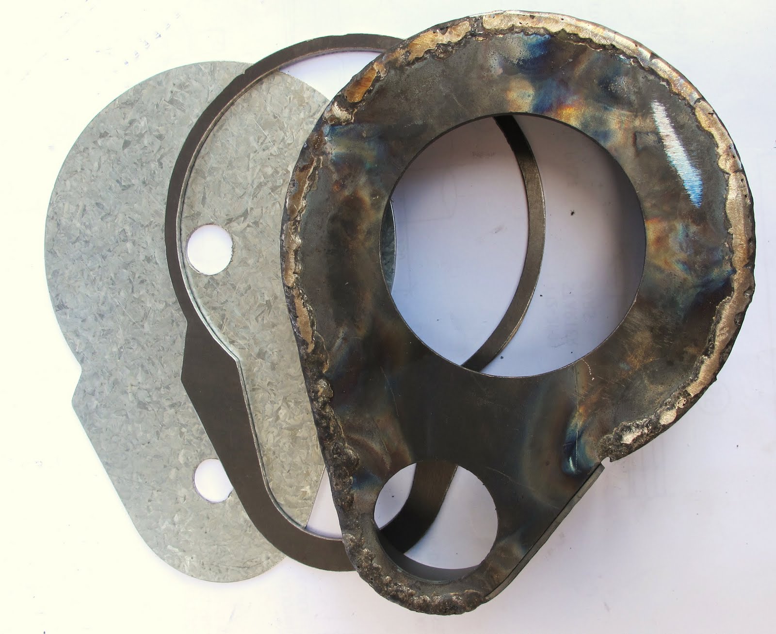


The inside profile of the clamp plate has been finished. About to cut the final shape.


Behind is the transmission mount plate, then the clamp plate (from above) and the gear cover partially fabricated using oxy welding and monel filler wire. This was done for strength so that it did not fall apart on subsequent operations. The mounting plate and ribs (shown later) were brazed on.


Left and right gear covers. Showing right hand cover (on left) before fabrication.


Here is the cover in place. Also seen here is the drive hub with studs where the drive sprocket attaches.


The completed cover temporarily fixed with cap screws to the transmission. These screws will be replaced with hex headed 3mm bolts.


Note the cap bolted to the outside of the cover. This houses the outer pinion ball-race.


Gear box

This shows one of the eight gears being hobbed by the system described in Model Engineers Work Shop magazine of October
2003. The 90 to 1 rotary table is driven by a stepper motor by 2 to 1 tooth belt. The hob shaft drives an encoder by tooth belt to generate 18,000 pulses per revolution.Synchronism is achieved by
three numbered digital switches. The number of teeth required is dialled, the table is set to cut parallel teeth, the gear blank of correct diameter is fixed to the rotary table by a morse taper arbor. The teeth are cut in one pass


This is the gear cluster mounted in the case before the bottom was welded in place. The gear at the top is low gear which meshes with the reverse gear idler cluster.


This is the final drive shaft with steering clutches and bevel gear.
The bevel gear and pinion shaft were salvaged from a disk sander .


This is the gearbox cluster and spline shaft. The spline shaft extends through the rear of the transmission as the power take-off. The cluster shows from the left, low gear, top gear in the centre and second gear on the right.


This is half of the ball cage for the throw-out bearing (part of the steering clutch) being machined from brass. Two sides are riveted together capturing the 16 1/8" balls. There is one for each clutch.


The completed thrust bearings.

Saturday, October 16, 2010

Transmission - Gearbox

Here the transmission is mounted to the lazy axle and the rear power take-off shaft can be seen coming out the rear of the transmission. This shaft on the prototype has a splined coupling to allow the steering clutches to be removed. The shaft on the model has been left in one piece to allow easy alignment of the bearings. The main clutch is at the other end of this shaft.


The aperture at the front of the gearbox is to allow the removal of the gear cluster and sliding gears. The gear cluster mounts to the lower shaft and drives the bevel gear. The panels on the bottom and sides of the gearbox will be fitted after the reverse gear idler shaft has been installed.


Transmission - Power Take-off and Drive shafts

This is the power take-off shaft. It is being reduced with an external hone from 16mm to 5/8" to fit the available bearings. This produces a very high precision, parallel result.


The shaft is mounted in a chuck attached to a dividing head. The spline requires 9 teeth. These are marked in red on the dividing plate.


The splines are cut with a tungsten carbide D bit profiled to the involute section.


The cutter runs at 250 RPM at a feed rate of 25mm per minute.

Transmission - Mounts

The mounts were profiled in the mill. The mount is 25mm high and each cut was about 1.5 mm deep.
This is one of four mounts. They will be brazed to the rear of the gearbox. These sit on the lazy axle.


The matching caps were machined on the lathe and milled to half diameter. They were then mounted on the mill and four recesses milled to receive the bosses which were then brazed on.


Here you can see one of four assembled mounts and the partially completed end caps. The small bosses were brazed on with nickel; bronze.


The four mounts brazed to the transmission housing and end caps before assembly.


The rear of the transmisssion has been bored for the rear power take-off.